31. Mechanical Installation
Learning objectives
- Execute the mechanical install in sequence to spec.
- Maintain flashing, torque, and bonding quality throughout.
31.1 The mechanical sequence
- Layout per the approved plan, marking rafter locations and honoring IFC setbacks/pathways (Ch 26).
- Attachments: install flashed standoffs/feet into structure (Ch 24/26), each torqued to spec.
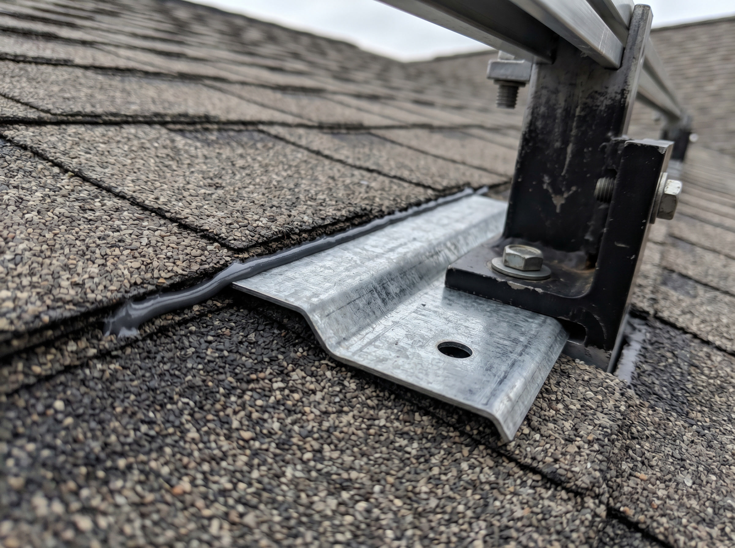 Figure 31.2: Step flashing tucked under the upslope shingle course; mount and sealant over it. Water sheds over the flashing, never under.
- Racking: assemble and level rails; establish equipment bonding with UL 2703 hardware (WEEBs/clips, Ch 22).
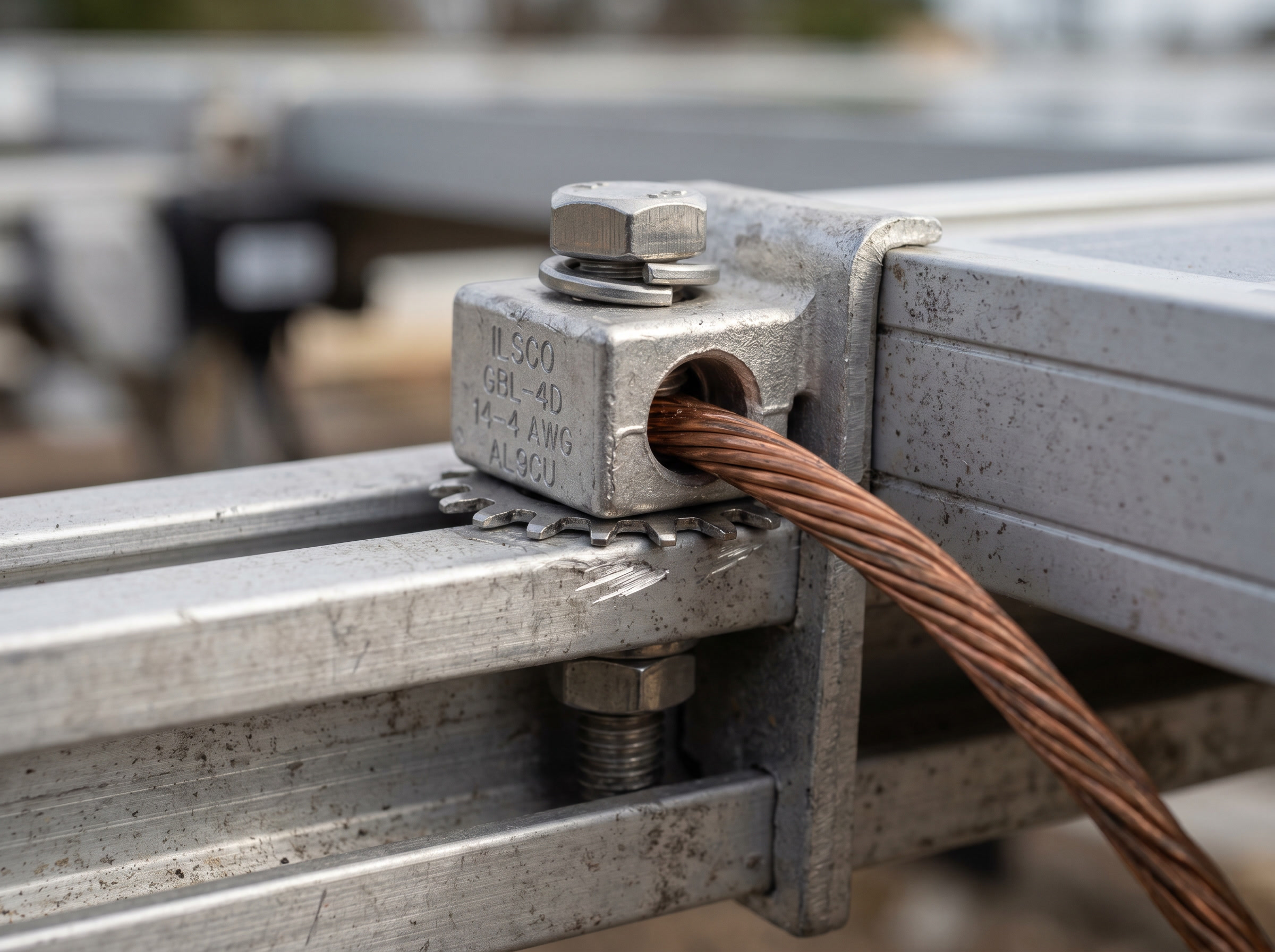 Figure 31.3: Equipment bonding: a listed lug / toothed washer bonds the module frame and rail, with a bare copper equipment-grounding conductor.
- Modules: set and secure with listed clamps at specified torque, maintaining the bonding path across the array.
- Conductor management: support wiring in UV-rated clips, off the roof surface, protected from abrasion.
31.2 Quality is in the repetition
Every penetration flashed, every bolt at torque, every bond made: there are no minor steps. A single unflashed foot leaks; a single loose clamp becomes a wind-loosed module. ⚠️ Torque-document with a calibrated tool; “hand-tight” is not a spec.
31.3 The mechanical sequence (and its quality triad)
 LAYOUT ─► ATTACH ─► RACK ─► SET MODULES ─► MANAGE WIRE
 (plan,    (flashed   (level  (listed clamps  (UV clips,
  setbacks, standoffs  rails,  at torque,      off the roof)
  rafters)  to struct, UL 2703 keep bonding)
            torqued)   bonding)
                    │
        every attachment point: FLASH ─ TORQUE ─ BOND
⚠️ Quality is the disciplined repetition of flash-torque-bond. One unflashed foot leaks; one loose clamp becomes a wind-loosed module; one missed bond breaks the grounding path. Torque with a calibrated tool and document it: “hand-tight” is not a spec. Torque values are product-specific; always consult the manufacturer’s installation instructions.
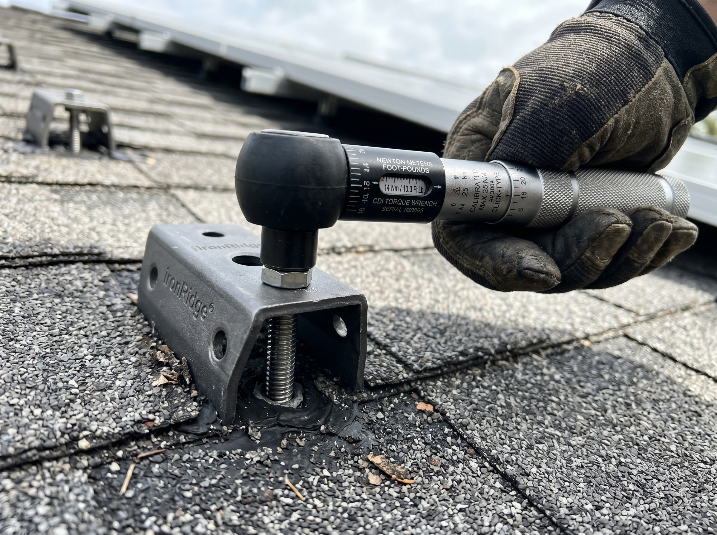 Figure 31.1: Torque every structural fastener to the manufacturer’s spec with a calibrated wrench (values are product-specific).
Chapter 31 summary
Lay out to plan and setbacks; install flashed, torqued attachments into structure; assemble level racking with UL 2703 bonding; set modules with listed clamps at torque; manage conductors off the roof. Quality is the disciplined repetition of flash/torque/bond on every point.
- IFC (International Fire Code): model fire-safety code that sets rooftop PV setback and pathway requirements.
- Flashed standoff/foot: a roof-penetrating mount sealed with step or counter-flashing so water sheds over, never under, the penetration.
- UL 2703: the listing standard for integrated PV racking and bonding systems; hardware listed to it provides the equipment-bonding path across the array.
- Listed clamp: a module-securing device evaluated and marked to a recognized standard (UL or equivalent), required by NEC for the bonding path.
- Flash/torque/bond: the three quality actions required at every attachment point; each must be completed and documented.
Full definitions: Appendix A (glossary).
Practice Problems: Chapter 31
- What three quality actions must happen at essentially every attachment point?
- Why document torque with a calibrated tool rather than tightening by feel?
- What provides the equipment-bonding path across a modern racking system?
- What’s the consequence of a single loose module clamp in a high-wind event?
Solutions: Chapter 31
- Flash, torque, bond.
- Under- or over-torque both fail (leaks/loosening or stripped/cracked); a calibrated, documented torque is verifiable for QA and warranty.
- UL 2703-listed bonding hardware (WEEBs, clips, lugs) integrating the rails/clamps into the grounding path.
- The module can work loose and become a wind-launched hazard, plus a broken bond/electrical fault.