30. Site Assessment & Survey
Learning objectives
- Capture the field data that confirms or corrects the design.
- Evaluate roof, shade, electrical, and structural readiness.
30.1 Measuring reality
A design built from satellite images must be verified on site. The survey captures:
- Roof: precise measurements, pitch, true azimuth, covering type and remaining life (don’t put a 30-year array on a 5-year roof), and accessible structure (rafter/truss size and spacing).
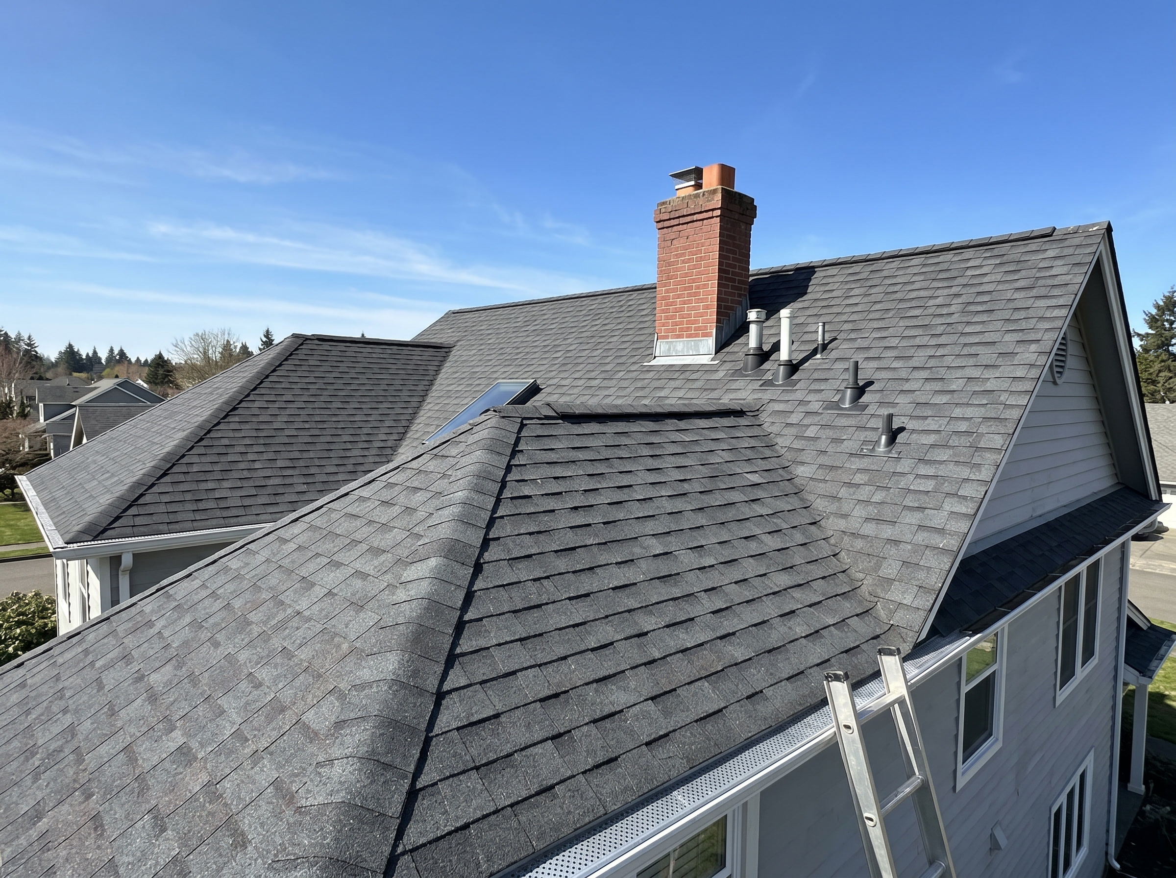 Figure 30.5: Roof planes, orientation, condition, and obstructions (chimney, vents).
- Shade: a real TSRF/solar-access reading across the 9–3 window (Ch 18) with a Solar Pathfinder, drone, or app, not an assumption.
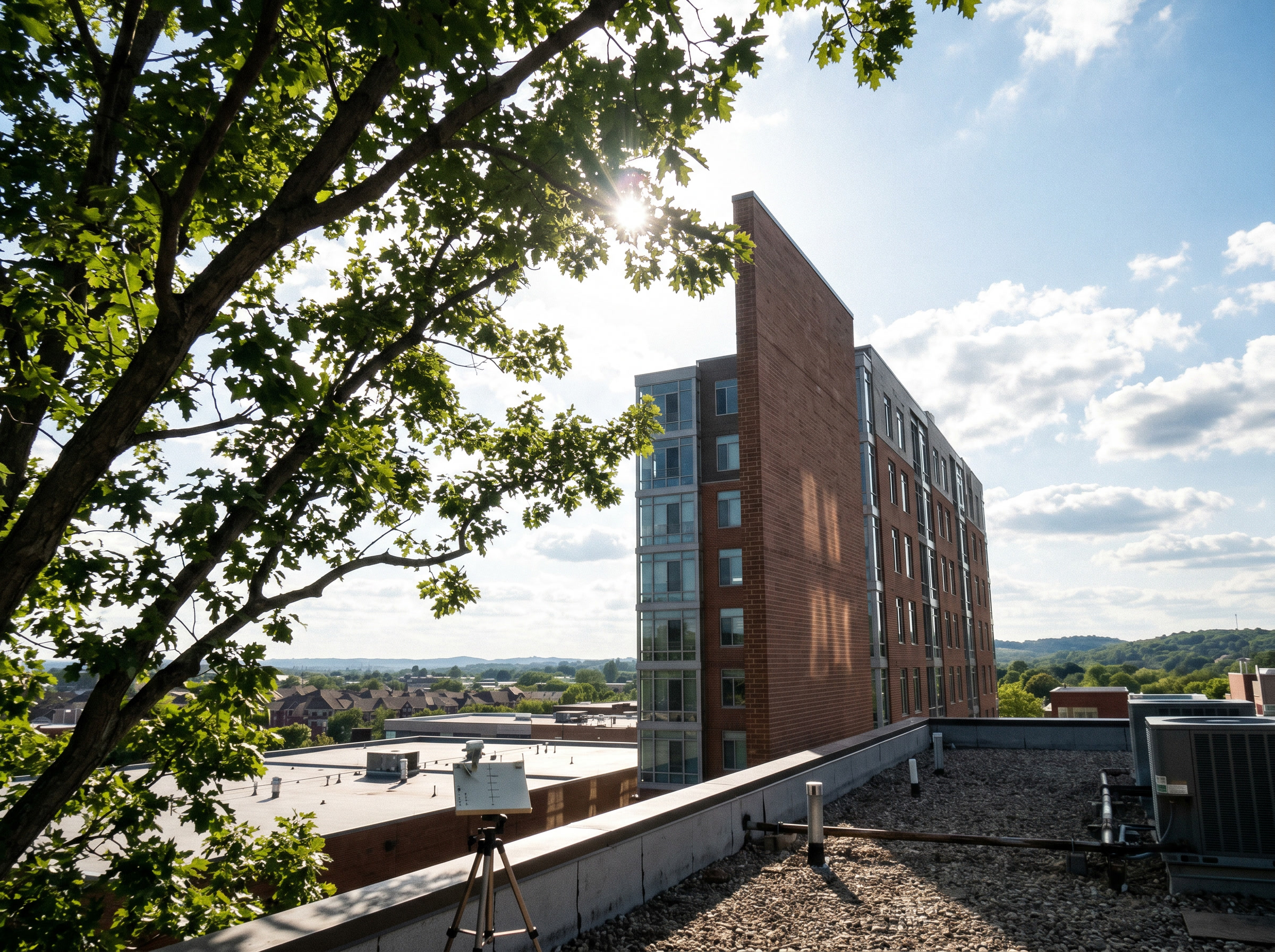 Figure 30.3: Shading / solar-window assessment toward the equator-facing sky.
- Electrical: service rating (busbar and main breaker → the 120% rule, Ch 16.4), meter and main locations, the interconnection point, and available breaker space.
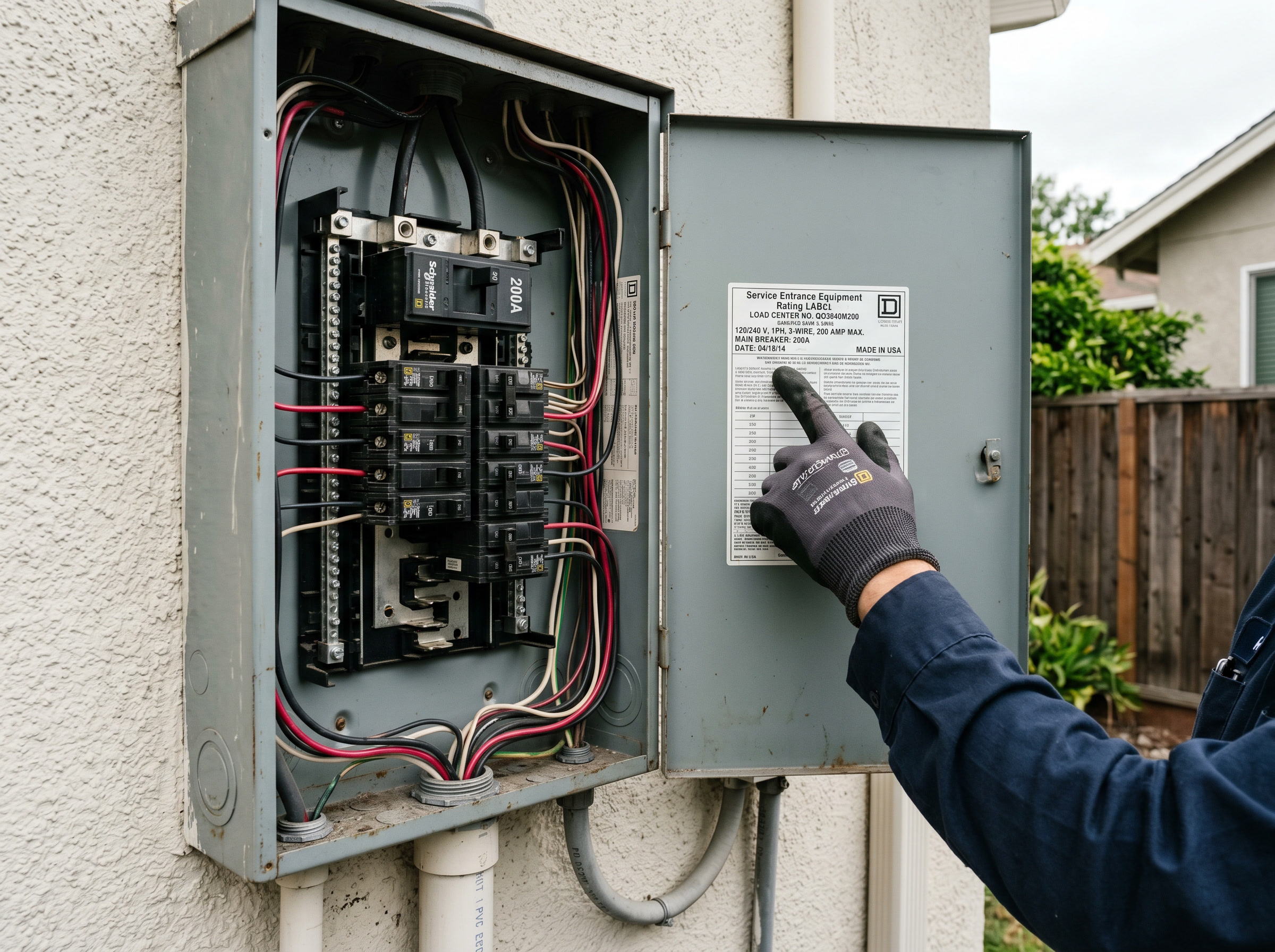 Figure 30.1: Service panel: photograph and read the rating label (main-breaker / busbar rating): it drives interconnection sizing.
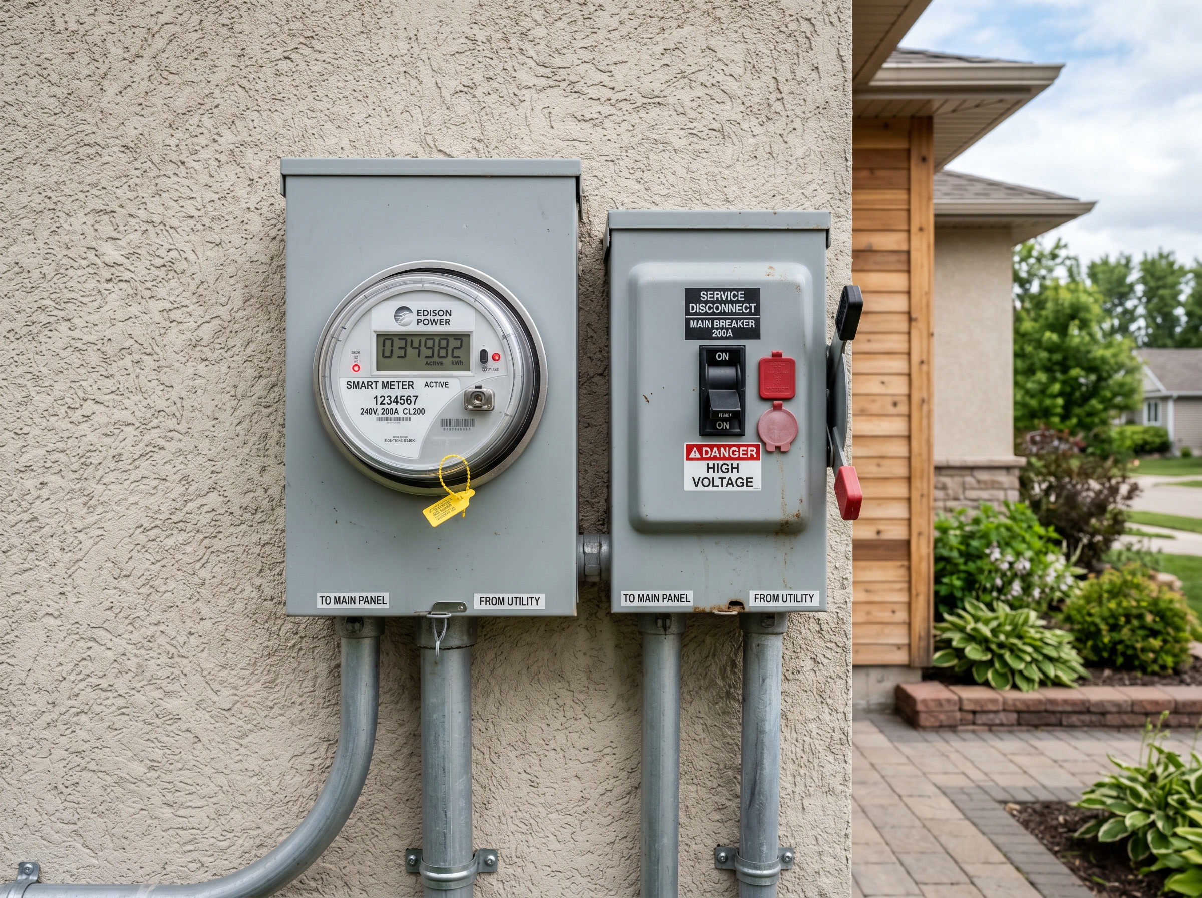 Figure 30.2: Utility meter and service disconnect (interconnection point of reference).
- Structure: confirm framing adequacy for the added dead load (Ch 25) and flag anything marginal for an engineer.
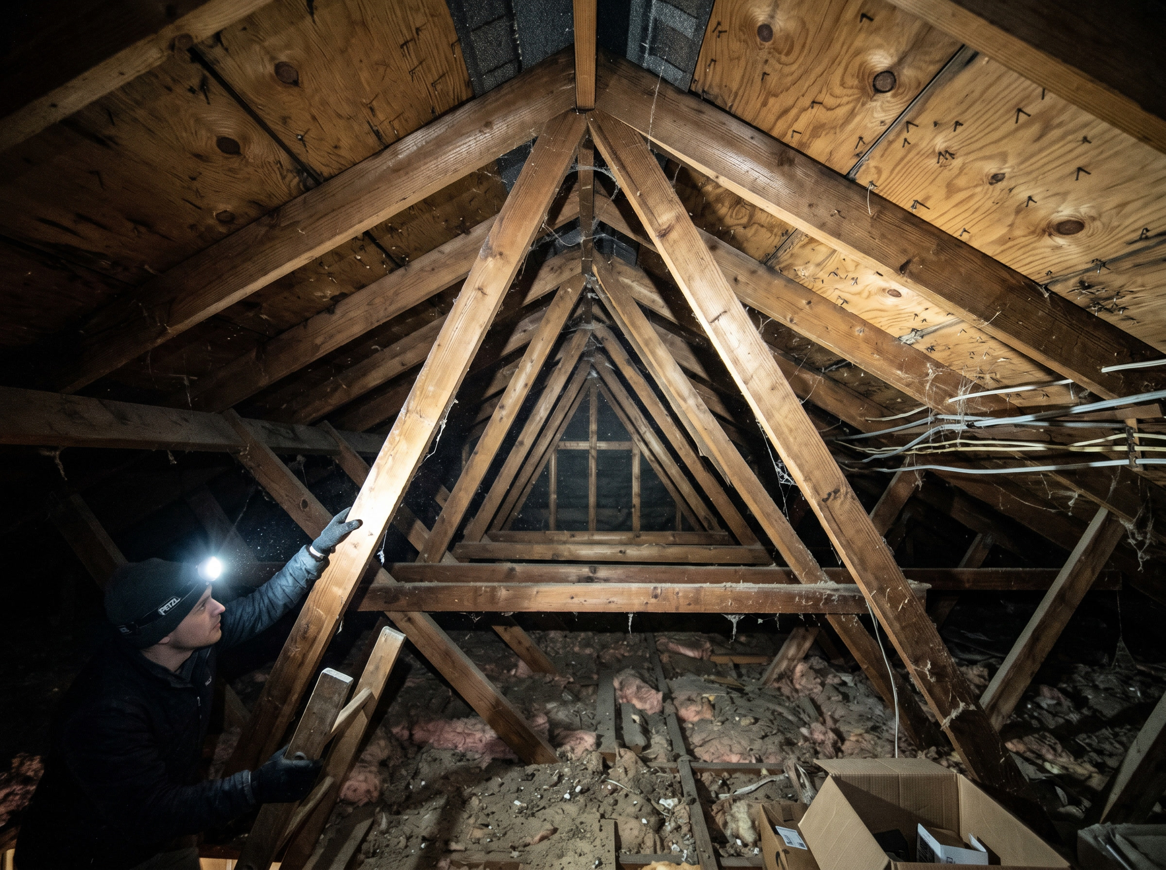 Figure 30.4: Attic / structure: rafter size and spacing for attachment.
- Logistics: equipment access, conductor routing paths, and inverter/disconnect/storage locations.
30.2 Document everything
Photos, measurements, and notes from the survey become the basis of the final plan set and protect against disputes. A reroof recommendation, a too-small service, or a shaded ridge discovered now is cheap; discovered after install, it’s a disaster.
30.3 Site survey checklist
 ROOF      ☐ measurements ☐ pitch ☐ true azimuth ☐ covering type & remaining life
           ☐ rafter/truss size & spacing ☐ obstructions (vents, chimneys, skylights)
 SHADE     ☐ TSRF / solar access across 9–3 window (Pathfinder/drone/app)
 ELECTRICAL☐ service rating (busbar + main) ☐ meter & main location
           ☐ interconnection point ☐ available breaker spaces ☐ 120% rule headroom
 STRUCTURE ☐ framing adequacy for added dead load ☐ engineer flag if marginal
 LOGISTICS ☐ equipment access ☐ conductor routing ☐ inverter/disconnect/ESS locations
 RECORD    ☐ photos ☐ measurements ☐ notes for the plan set
Chapter 30 summary
Verify the design in the field: roof geometry/condition/structure, real shade access, service rating and interconnection point, structural adequacy, and site logistics, all documented. Catching problems here is the cheapest they’ll ever be.
- True azimuth: compass bearing from true (geographic) north, used to quantify a roof surface’s actual solar exposure.
- TSRF (Total Solar Resource Fraction): site-measured percentage of available solar resource reaching the array after shading, tilt, and orientation losses.
- 120% rule (NEC 705.12): the busbar-loading limit that sets the maximum PV breaker size for a given service panel.
- Interconnection point: the electrical connection between the PV system and the utility grid or building service, established during the survey.
- Solar-access window (9–3): the 9 a.m.–3 p.m. period used for shade assessment; shading losses outside this window have minimal production impact.
Full definitions: Appendix A (glossary).
Practice Problems: Chapter 30
- Why check the roof covering’s remaining life during the survey?
- Which electrical figure determines how much PV you can back-feed onto the panel, and which rule uses it?
- A satellite-based design assumed an unshaded roof; the survey finds a tall tree to the south. What changes?
- Name two things that, if discovered post-install instead of at survey, become expensive disasters.
Solutions: Chapter 30
- So you don’t mount a 25–30-year array on a roof needing replacement in a few years (forcing a costly removal/reinstall).
- The service/busbar rating (with the main breaker), used by the 120% busbar rule (Ch 16).
- The real TSRF drops; production estimates and possibly the array layout/size must be revised, or MLPE added to limit shade losses.
- Any two: a too-small service, a roof needing replacement, shading that guts production, or inadequate structure: all are cheap to fix on paper, ruinous after install.