32. Electrical Installation
Learning objectives
- Wire the DC and AC sides correctly and safely.
- Complete grounding/bonding and the interconnection.
32.1 DC side
Wire source circuits in sunlight-rated conductors with listed, brand-matched MC4-type connectors (Ch 8), confirming polarity. Mount MLPE if used. Land strings in combiners where applicable and transition to raceway when leaving the array vicinity (690.31). ⚠️ The array is live throughout: energized-DC discipline (Ch 28) applies from the first module connected.
32.2 Inverter and AC side
The installation sequence runs DC source circuits → inverter → AC output → grid interconnection. Mount and wire the inverter (DC in, AC out), install the required DC and AC disconnects, and complete the AC interconnection: either a load-side breaker honoring the 120% busbar rule or a line-side/supply-side tap governed by NEC 705 for larger systems (Ch 16.4).
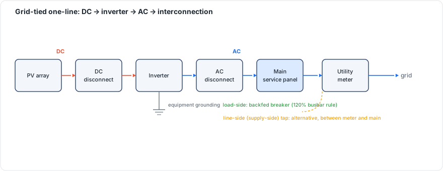 Figure 32.1: Grid-tied one-line: DC → inverter → AC → interconnection, showing load-side (backfed breaker, 120% rule) vs line-side (supply-side) tap. Original figure.
32.3 Grounding and labeling
Complete the equipment grounding (EGC) across all metal and the grounding-electrode connection (GEC) per 690.41–690.47 (Ch 22). Apply the full label set for your adopted code edition (Ch 23).
Chapter 32 summary
Wire DC source circuits (polarity, listed connectors, raceway transitions), mount/wire the inverter with DC and AC disconnects, and interconnect via the 120% rule or a line-side tap. Finish grounding/bonding (EGC + GEC) and edition-correct labeling, all under energized-DC discipline.
- Source circuit: wiring from a module or string to the first overcurrent protection or combiner.
- MLPE (Module-Level Power Electronics): per-module microinverters or DC optimizers for individual shutdown and power tracking.
- Raceway: an enclosed conduit or wireway protecting conductors leaving the array vicinity.
- 120% busbar rule: NEC 705.12(B) limit allowing a backfed PV breaker within 120% of the busbar rating.
- EGC (Equipment Grounding Conductor): bonds metal parts together for fault-current return.
- GEC (Grounding Electrode Conductor): ties the grounded system to the building’s grounding electrode.
Full definitions: Appendix A (glossary).
Practice Problems: Chapter 32
- Why is verifying polarity before interconnecting strings so important (and when is it tested, Ch 33)?
- What two interconnection methods exist when a load-side breaker won’t fit under the 120% rule?
- What safety discipline governs the entire DC-side wiring process?
- Name the two grounding connections completed during electrical install.
Solutions: Chapter 32
- Reversed polarity can damage equipment and is dangerous; it’s checked before strings are interconnected during commissioning (IEC 62446 step 2, Ch 33).
- A line-side (supply-side) connection or a busbar derate/service upgrade.
- Energized-DC discipline: the array is live in daylight throughout.
- The EGC (equipment bonding/fault path) and the GEC (to the grounding electrode).