35. Troubleshooting & Fault Diagnosis
Learning objectives
- Diagnose faults by systematic isolation.
- Recognize common PV fault signatures and the tools that find them.
35.1 Systematic isolation
Diagnose top-down: system → string → module. Inverter fault codes and monitoring narrow the location; then the commissioning tests (Voc/Isc/insulation resistance/I-V trace, Ch 33) become diagnostic tools to isolate the fault.
35.2 Common faults and tools
- Open circuits: frequently caused by a failed/mismatched MC4 connector (Ch 8.2), a leading real-world failure point.
- Ground faults: found by insulation-resistance testing.
- Hot spots / cell or diode failures: found with a thermal camera (IEC 62446-3 aerial thermography on larger sites). On a thermal image, a single bright cell against cooler neighbors indicates a cell-level defect or shading. A full-module hot zone points to a bypass-diode failure.
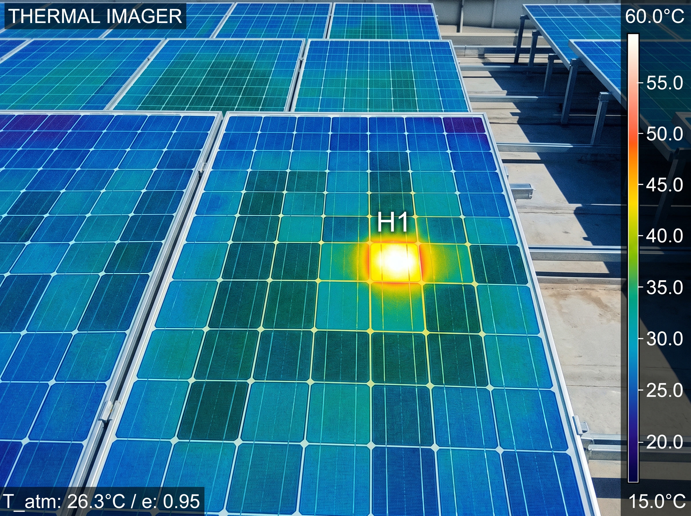 Figure 35.2: Infrared (IR) thermography reveals a hot cell / hot-spot, a fast non-contact field diagnosis.
- Underperformance: soiling, encroaching shade, or module degradation (Ch 5.5), confirmed by I-V tracing against the datasheet. A healthy trace shows a square knee. A sloped knee indicates elevated series resistance (connection loss or cell degradation). A step or notch in the curve is the signature of partial shading or a bypass diode activating.
 Figure 35.1: I-V tracer signatures: healthy vs series-resistance vs shaded. Original figure.
- Inverter faults: read codes; many are grid- or temperature-related. ⚠️ The same energized-DC discipline (Ch 28) governs every troubleshooting visit.
35.3 Troubleshooting decision tree
 Underperformance / fault flagged
        │
        ▼
 Whole system down? ──YES──► Check inverter status/fault codes ─► grid/AC issue?
        │NO                                                       temp shutdown? GFP trip?
        ▼
 One string/zone low? ──YES──► Voc test: open circuit? (failed connector / broken lead)
        │                       Isc test: low? (shading/soiling/mismatch)
        │                       Insulation test: low? (ground fault)
        ▼
 One module low? ──► Thermal scan: hot spot? (cell/diode failure)
        │            I-V trace vs datasheet: degradation?
        ▼
 Confirm fix → re-test (commissioning tools) → document
   ⚠️ all steps under energized-DC discipline (Ch 28)
Faults are isolated top-down (system → string → module), and the commissioning tests (Ch 33) double as the diagnostic toolkit.
Chapter 35 summary
Isolate faults system→string→module using monitoring plus the commissioning test set. Watch for connector-driven opens, ground faults (insulation test), hot spots (thermal imaging), and degradation/soiling (I-V trace), all under live-DC safety discipline.
- MC4 connector: a 4 mm-contact weatherproof DC cable connector; mismatched or failed MC4s are a leading cause of open circuits.
- Insulation-resistance test: high-potential DC leakage test; a low reading signals a ground fault or damaged insulation.
- Bypass diode: a diode inside a module that routes current around shaded or faulted cells to prevent hot spots.
- I-V trace: a current-vs-voltage curve swept by a tracer instrument; curve shape reveals healthy, degraded, or shaded conditions.
- Hot spot: a localized overheating region on a module caused by a cell defect, mismatch, or bypass-diode failure.
- Top-down isolation: fault-finding sequence from system level to string to individual module.
Full definitions: Appendix A (glossary).
Practice Problems: Chapter 35
- What is the general order of fault isolation?
- A string reads open-circuit (no current). What’s a common physical cause?
- Which test finds a ground fault? Which finds a hot spot?
- Monitoring shows one module underperforming while its neighbors are fine. Which fault category does that point to, and which tool confirms it?
- The whole system is offline at midday with a grid-related inverter code. Is this most likely an array fault or something else?
Solutions: Chapter 35
- System → string → module (top-down isolation).
- A failed/mismatched MC4 connector or broken lead (open circuit).
- Insulation-resistance test finds ground faults; a thermal camera finds hot spots.
- A module-level fault (cell/diode failure or local shading/soiling); confirm with thermal imaging and/or an I-V trace.
- Likely not an array fault. A grid/AC condition (voltage/frequency excursion) or anti-islanding trip is the probable cause; check grid status and inverter codes first.