8. Balance of System (BOS)
Learning objectives
- Identify the conductors, connectors, and protective devices that tie a system together.
- Match wire types and connectors to PV’s environmental and electrical demands.
- Explain the role of combiners, disconnects, and overcurrent protection at a component level (sizing comes in Part IV/V).
8.1 Conductors
PV wiring lives in brutal conditions (UV, heat, moisture), so it uses purpose-rated cable:
- PV Wire (listed to UL 4703) and USE-2: for exposed DC source/output circuits, sunlight-resistant and rated for wet locations at 90 °C+.
- THWN-2: common in conduit for inverter outputs and AC runs.
Conductor ampacity (current capacity) must exceed the circuit’s current after temperature and conduit-fill derating: the core calculation of Chapter 16.
8.2 Connectors
Module-to-module and string connections use listed locking DC connectors, the MC4 type being near-universal. “MC4” stands for Multi-Contact 4 mm (the contact-pin diameter); Stäubli is the original manufacturer. The connectors are intentionally polarized (separate male/female bodies). No international standard governs the physical pin geometry across brands, so only connectors from the same product family are listed to mate.
⚠️ Cross-mating hazard: joining a male of brand A to a female of brand B (“MC4-compatible” parts) is the core connector danger. A physically clicked pair is not a certified one. Consequences include cracking, moisture ingress, and rising contact resistance, which causes localized heating, power loss, and at worst fire. The damage is often invisible on inspection. IEC 62852/EN 62852 and installation norms IEC 62548 require that connectors “shall be of the same type from the same manufacturer.” Mixing brands voids the connector’s certification and is a code violation. Treat brand-and-model match as a requirement, not a preference.
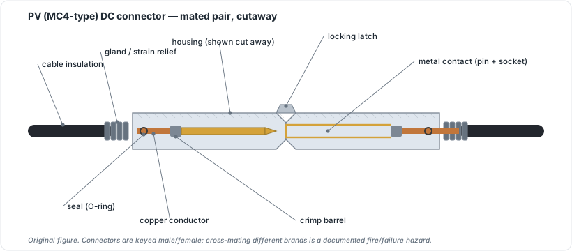 Figure 8.1: PV (MC4-type) DC connector, mated pair, cutaway. Original figure.
8.3 Combiners, disconnects, and protection
- Combiner box: where multiple source circuits are paralleled. Internally, the path runs: string fuses (gPV class, DC-rated) to positive and negative busbars (the paralleling point) to a DC disconnect to the single output conductor. ⚠️ Paralleling strings adds current, not voltage: four 10 A strings combined yield ~40 A at one string’s voltage, a common point of confusion.
- String fuses must be DC-rated (gPV class, IEC 60269-6); AC fuses cannot safely interrupt DC fault current (no zero-crossing). Sizing rule: fuse >= Isc × 1.25 × 1.25. Example: Isc 10.5 A → minimum 16.4 A → next standard 20 A fuse (confirm this is at or below the module’s max series-fuse rating).
- SPD placement: the surge protective device belongs inside the combiner box, as close to the array as practical. Installing the SPD at the DC combiner input clamps lightning-induced transients before they reach the inverter and downstream conductors. ⚠️ Safety note: turning the inverter off does not de-energize the combiner; modules remain live. Always isolate via the DC disconnect (with DC-rated PPE) before opening the combiner.
- Disconnects: code requires accessible means to de-energize: a DC disconnect (array side) and AC disconnect (inverter output), enabling safe service and emergency shutoff.
- Overcurrent protection devices (OCPD): fuses/breakers protecting conductors; sized by the methods in Chapter 16/23.
- AFCI/GFCI: arc-fault and ground-fault protection (often built into modern inverters) that detect dangerous faults and shut down.
- Wire management: UV-rated clips/conduit keeping conductors off the roof and organized; sloppy management is both a code and a longevity problem.
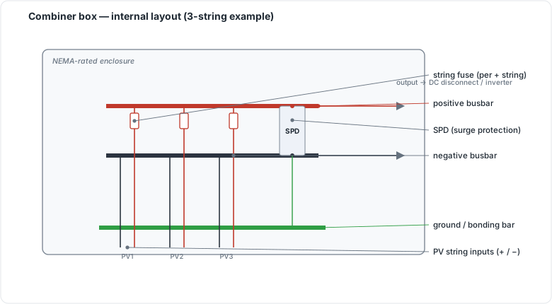 Figure 8.2: Combiner box internal layout (string fuses, busbars, SPD, ground bar). Original figure.
8.4 The BOS wiring path
 [modules]──PV wire/USE-2──[MC4 connectors]──[combiner + string fuses]──┐
                                                                         │
   [DC disconnect]──────────────────────[INVERTER]───[AC disconnect]──[panel/grid]
        │                                  │
   surge protection (SPD)            AFCI/GFCI (often integral)
   ── conductors UV/wet-rated, sized by ampacity AFTER temp + conduit-fill derate (Ch 16) ──
⚠️ Use listed, brand-matched connectors; mixing “looks-like-MC4” brands is a code violation and a real fire/failure point (Ch 8.2).
Chapter 8 summary
BOS is everything between modules and the grid: sunlight/wet-rated conductors (UL 4703 PV wire, USE-2, THWN-2) sized by ampacity after derating; listed, brand-matched MC4-type connectors; combiners with string fusing; required DC and AC disconnects; OCPD, AFCI/GFCI, and surge protection; and disciplined wire management. The sizing of these is the work of Parts IV–V.
- BOS (Balance of System): all components between the modules and the grid: conductors, connectors, combiners, disconnects, overcurrent protection, surge protection, and wire management.
- PV Wire (UL 4703): sunlight-resistant, wet-rated cable listed for exposed DC source and output circuits.
- USE-2: underground-service-entrance cable also rated for PV DC circuits in wet/sunlight-exposed locations.
- Ampacity: the maximum continuous current a conductor can carry under specified conditions before derating.
- Derating: reducing rated ampacity to account for elevated temperature or bundled conductors in conduit.
- MC4 (Multi-Contact 4 mm): the near-universal locking DC connector type; brands must match within a mated pair.
- Combiner box: the enclosure where multiple source-circuit strings are paralleled through per-string fuses onto a common output.
- gPV class (IEC 60269-6): the DC-rated fuse class required for PV string protection; can interrupt DC fault current safely.
- SPD (Surge Protective Device): a component placed inside the combiner box to clamp lightning-induced transients before they reach the inverter.
- OCPD (Overcurrent Protection Device): a fuse or breaker that protects conductors from excess current.
- AFCI/GFCI: arc-fault and ground-fault circuit interrupters that detect dangerous faults; often integral to modern inverters.
Full definitions: Appendix A (glossary).
Practice Problems: Chapter 8
- Which conductor listing applies to exposed DC PV wire?
- Why is mixing connector brands that “look like MC4” a problem?
- What lives in a combiner box, and what does it protect?
- Name the two disconnects BOS provides around the inverter.
- Conductor ampacity must exceed the circuit current after what two adjustments?
Solutions: Chapter 8
- UL 4703 (PV wire).
- Different-brand connectors aren’t listed to mate; mixing them is a code violation and a failure/fire point.
- String fuses (and paralleling of source circuits); the fuses protect source-circuit conductors, sized to the module’s max series-fuse rating.
- The DC disconnect and the AC disconnect.
- Temperature correction and conduit-fill derating (Ch 16).